
Three Types of Injection Molds
Injection molds are classified by their gating and ejection mechanisms. The three most common types are:
Two‑Plate Mold
The two‑plate mold is the simplest and most widely used design. It splits along a single parting line into two halves – the core (moving side) and the cavity (fixed side). This straightforward structure makes it cost‑effective and suitable for a wide range of applications, especially where gate marks on the part perimeter are acceptable.
Three‑Plate Mold
The three‑plate mold opens along two parting planes, adding a stripper plate between the nozzle and the cavity plate. This design allows the use of pin‑point gates, which can be placed at any point on the part surface, leaving minimal gate vestiges. It is ideal for parts that require multiple injection points due to large projected areas or when aesthetic gate marks on the outer surface must be avoided. However, the three‑plate mold has a more complex construction and generally requires a larger machine opening stroke.
Hot Runner Mold
The hot runner mold retains the operational simplicity of a two‑plate mold while offering the gating flexibility of a three‑plate system – it can feed molten plastic from virtually any point within the cavity. More importantly, it eliminates the waste and pressure/temperature losses associated with cold runners, as the material in the runner remains molten throughout the cycle. This results in shorter cycle times, reduced scrap, and improved part quality. Although the initial tooling cost is higher, hot runner systems are a major advancement in gating technology, especially for high‑volume production and demanding aesthetic requirements.
Basic Structure of an Injection Mold
A complete injection mold consists of several functional systems, each playing a critical role in the molding cycle. The main components include:
Mold Base – The framework that supports and aligns all other components, typically consisting of clamping plates, support pillars, and guide pins.
Molding System – The core and cavity that define the shape of the final part.
Feed System – The channel through which molten plastic travels from the nozzle to the cavity, including sprue, runners, and gates (cold or hot).
Ejection System – Mechanisms (ejector pins, sleeves, or plates) that push the solidified part out of the mold after cooling.
Cooling System – Water channels or other cooling media that regulate mold temperature to achieve uniform cooling and optimal cycle times.
Venting System – Small grooves or clearances that allow trapped air to escape during injection, preventing burns, voids, or incomplete fill.
Guiding Structure – Guide pins and bushings that ensure precise alignment of the two mold halves during opening and closing.
Each of these systems must be carefully designed and integrated to achieve reliable, high‑quality injection molding performance.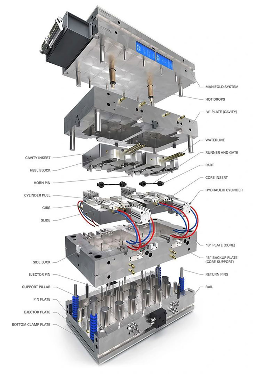
Injection Mold Structure – Key Components Explained
A precision injection mold is composed of multiple interconnected systems and components, each serving a specific function. Understanding these parts is essential to appreciating how a mold operates reliably over millions of cycles.
Mold Base Components
Top Clamp Plate – Also known as the fixed clamping plate, it connects the mold to the stationary platen of the injection molding machine and secures the A plate in position.
A Plate (Fixed Half) – Mounted to the front half of the mold, it holds the cavity side. In some designs, high-grade steel is used directly in the A plate to form the molding surface.
B Plate (Moving Half) – Attached to the rear half, it secures the core side and may also incorporate runner extensions.
Spacer Block (C Plate) – Positioned between the B plate and the rear clamp plate, it provides support for the mold base and creates space for the ejection system. Its height is determined by the product's ejection stroke requirements.
Rear Clamp Plate – Connects the mold to the moving platen of the injection machine, providing a mounting surface for the entire mold assembly.
Molding System (The Core of the Mold)
The molding system defines the shape, dimensions, and surface quality of the finished part. It is the most critical and time‑consuming part of mold manufacturing, as it directly determines product precision and consistency. The molding system primarily consists of the cavity, core, slides, lifters, and inserts.
Mold Cavity – Located in the fixed half (front) of the mold, the cavity forms the external shape of the part. It remains stationary during molding and must withstand high injection pressures. Its structure is generally simpler than that of the core.
Mold Core – Located in the moving half (rear), the core forms the internal geometry of the part. It moves with the mold opening and closing, and typically features a more complex structure with protrusions, ribs, and bosses.
The cavity and core work together as a matched pair. Their precise fit, robust construction, and balanced pressure distribution are essential for achieving high molding accuracy and prolonging tool life.
Slides (Side Cores) – These are components that move perpendicular to or at an angle to the mold opening direction. They are required when the part has side undercuts or holes that are not aligned with the opening direction. The principle is simple: the slide must retract before the part is ejected to avoid interference and potential damage.
Lifters (Angular Ejectors) – These are used to release internal undercuts (features on the inner surface of the part). The lifter moves along an angled path, driven by the ejector plate, to clear the undercut during ejection. This is especially important when the part has thin internal walls that could be damaged by standard ejector pins. The lifter's design is closely tied to the ejection stroke and requires precise angle calculation.
Inserts – These are individual components embedded within the mold, typically made of copper, steel, or other wear‑resistant materials, and can take various shapes (square, round, flat, etc.). Inserts serve multiple purposes: reinforcing plates, filling gaps, reducing core height to save material, facilitating mold modifications and repairs, improving venting, enabling machining of complex deep ribs, and extending overall mold life. When designing inserts, precise positioning features such as dowel pins or screw holes must be incorporated to ensure stability and repeatability.
